Maybe some of you guys might know a thing or two about old radio receivers, I think it's relevant...
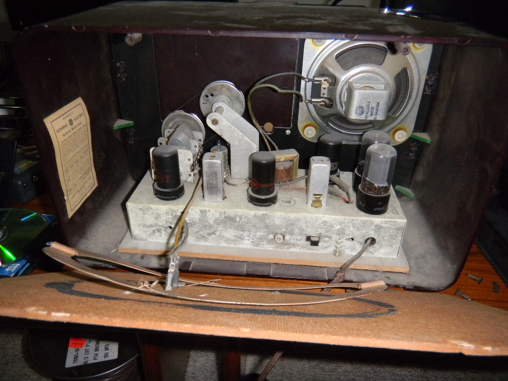
I have a General Electric C409 broadcast band receiver that was given to me today. Actually I have seen and heard it in operation many years ago, and it did work well.
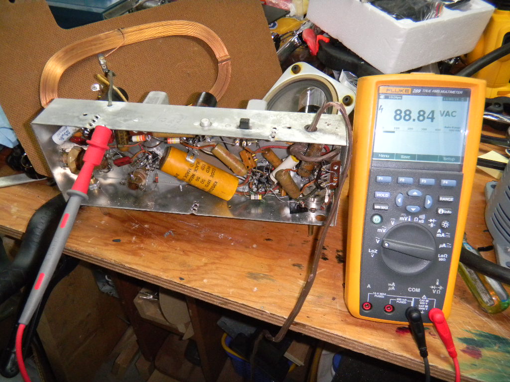
Today though, it puts out a 60Hz buzz over the audio. So, somewhere the AC line frequency is not getting filtered out.
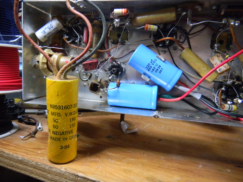
Now my thinking is that the capacitors are failing in the device and I need to replace them. These are the cardboard and wax kind.
What are modern equivalents that are acceptable replacements? I assume if I stick to non-polarized axial style components that would be the safest since I'm not sure of the polarities.
I wish I had a schematic for this, and I thought this was the era of gluing the schematics to the back panel. There is only a tube placement diagram.
Maybe I will string together some of my spare lead acid batteries to see if powering the unit with DC eliminates the hum.
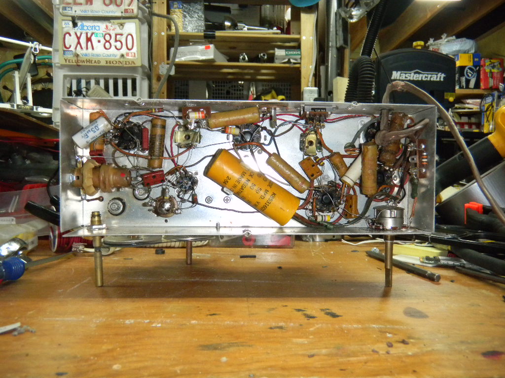
Peeking in through the back panel
Bottom of chassis
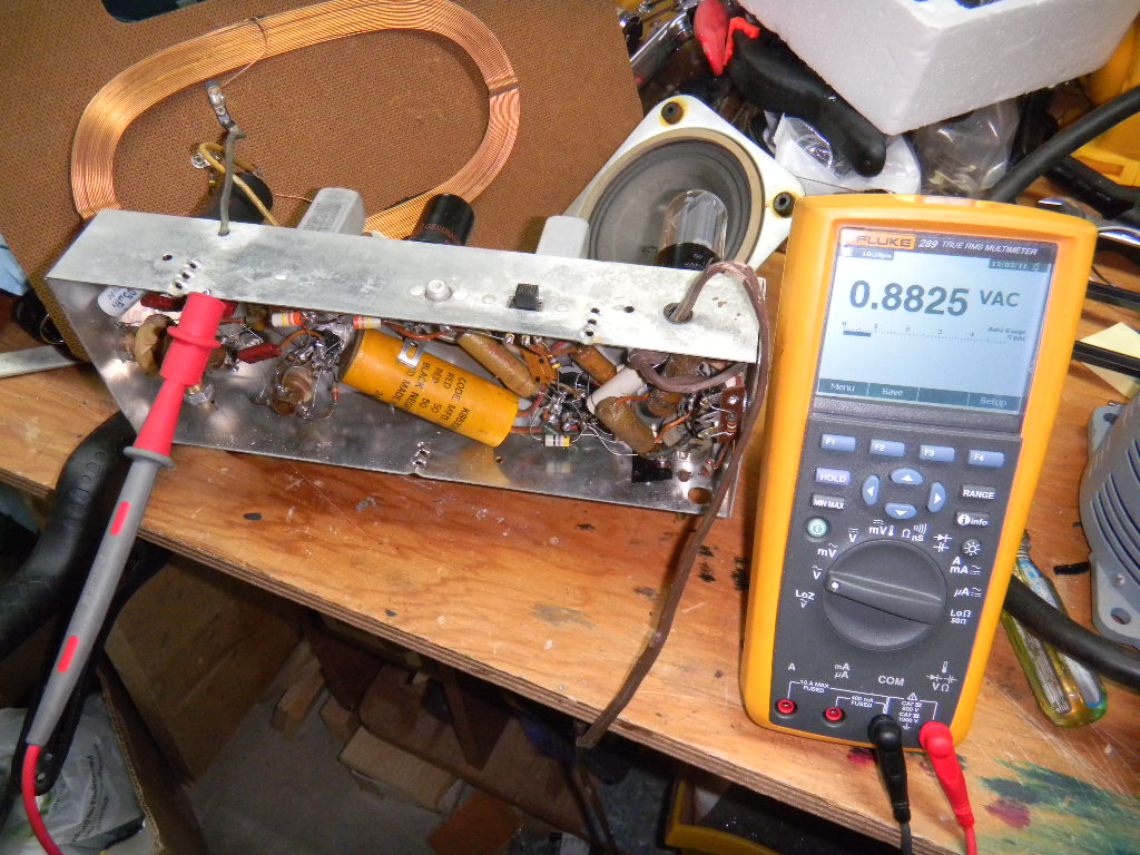
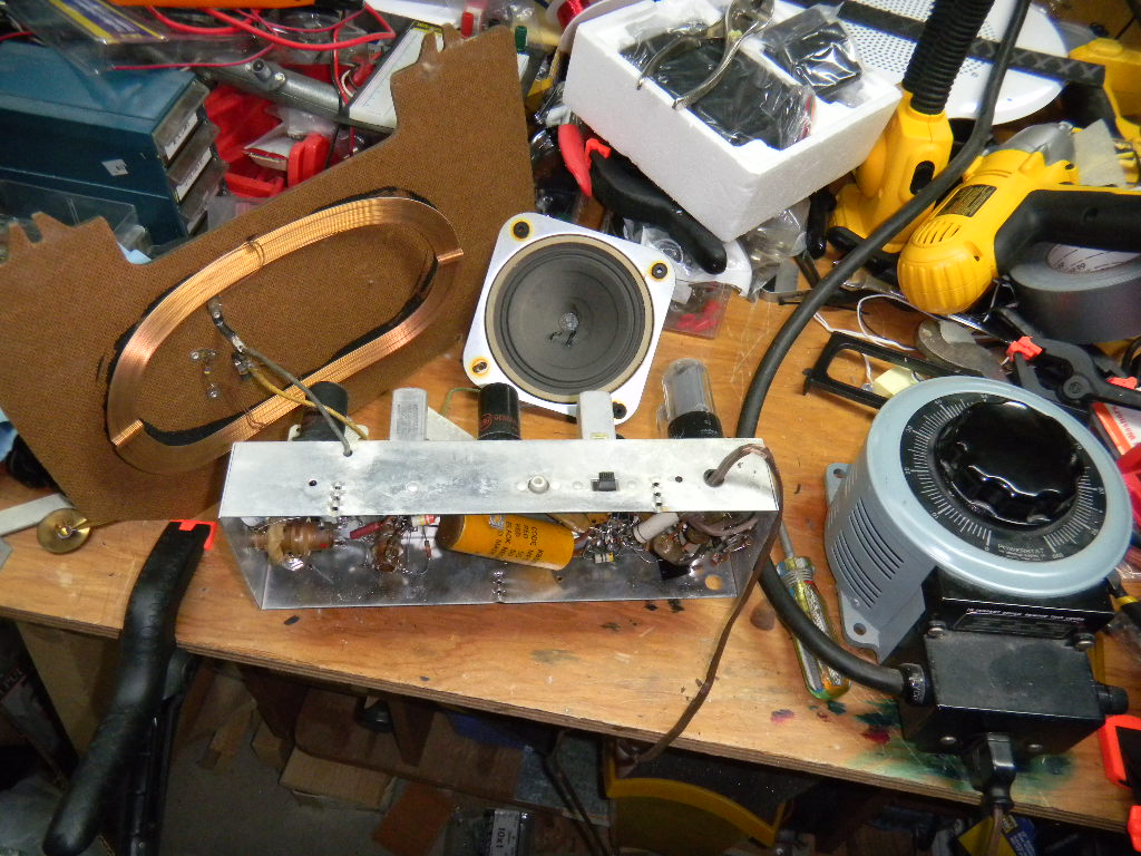
All components re-attached, operating at 50% off the variac.
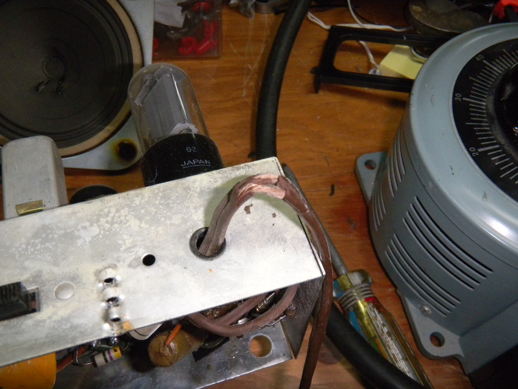
The power cord crumbles a bit more every time I touch it. Gotta change it out right away.
I made a small video clip demonstrating the issue. You can sorta make out CHQT 880 in the receive audio.
http://sandbox.ahtr.net/DSCN0916.AVI