Tube radio repair

News, discussion and questions about technology and computers, whether broadcast-related or not.

Tube radio repair

Postby TRENT310 » Sun Mar 13, 2011 8:58 pm

Ok, so ironically on this radio forum, I don't know which board is the most appropriate to ask a question about repairing radio hardware.
Maybe some of you guys might know a thing or two about old radio receivers, I think it's relevant...

I have a General Electric C409 broadcast band receiver that was given to me today. Actually I have seen and heard it in operation many years ago, and it did work well.
Today though, it puts out a 60Hz buzz over the audio. So, somewhere the AC line frequency is not getting filtered out.
Now my thinking is that the capacitors are failing in the device and I need to replace them. These are the cardboard and wax kind.
What are modern equivalents that are acceptable replacements? I assume if I stick to non-polarized axial style components that would be the safest since I'm not sure of the polarities.
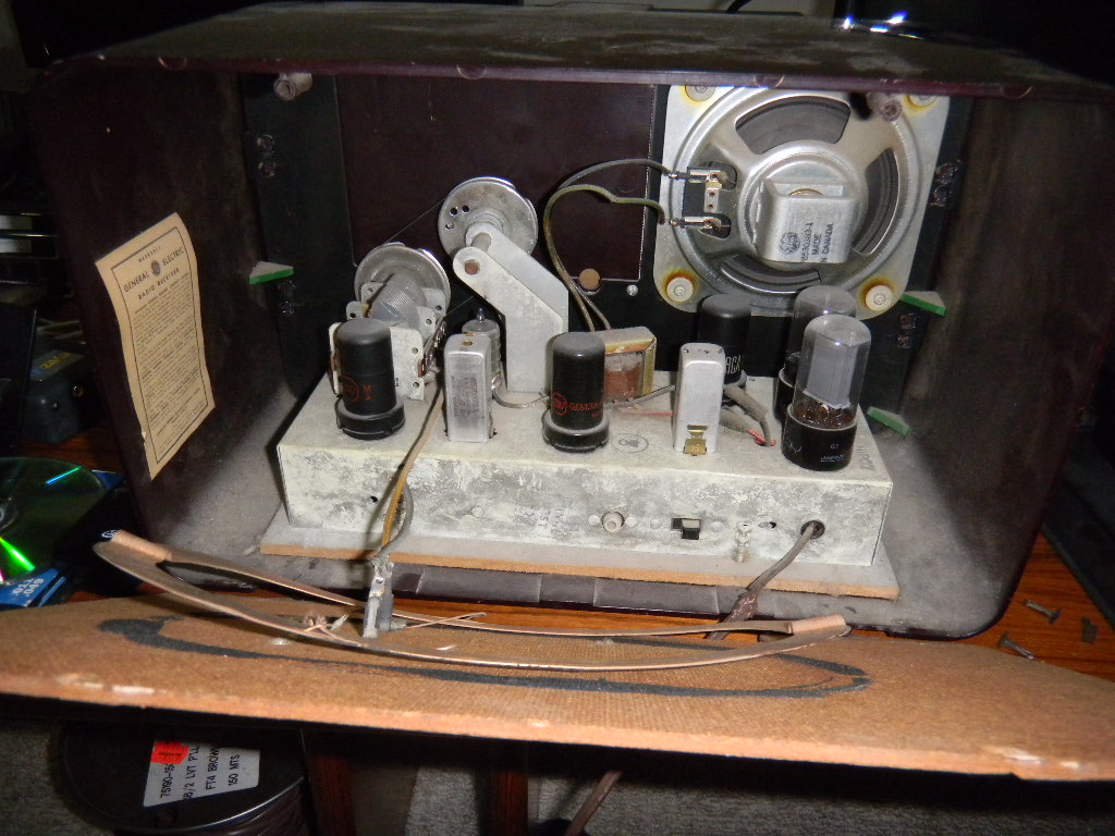
I wish I had a schematic for this, and I thought this was the era of gluing the schematics to the back panel. There is only a tube placement diagram.

Maybe I will string together some of my spare lead acid batteries to see if powering the unit with DC eliminates the hum.

Peeking in through the back panel
Image

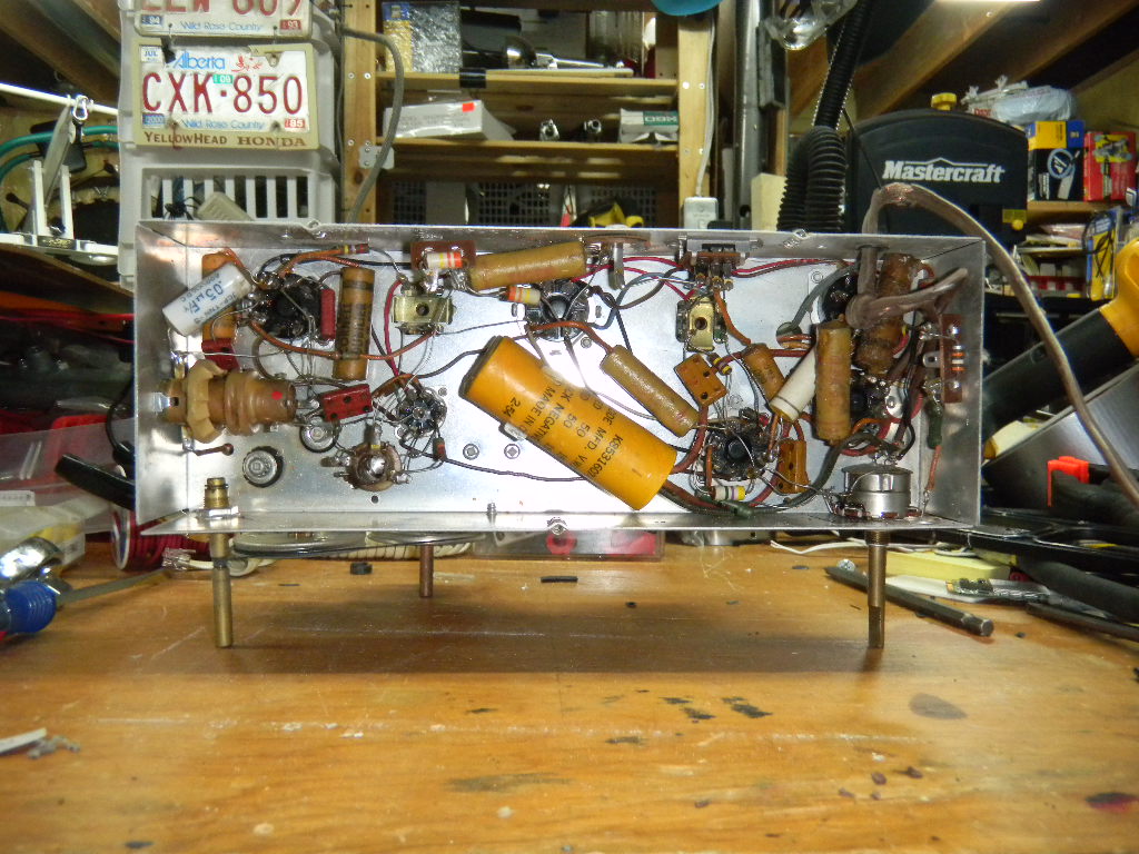
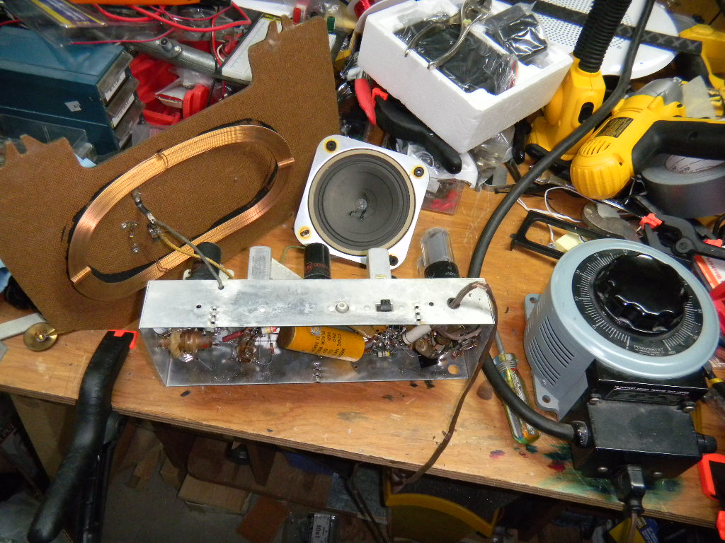
Bottom of chassis
Image

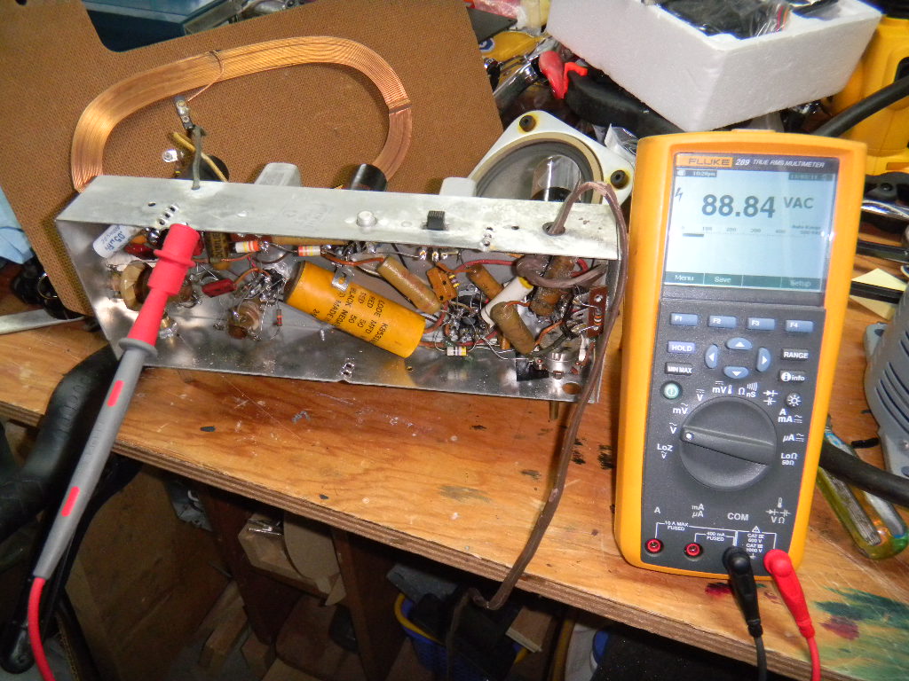
All components re-attached, operating at 50% off the variac.
Image

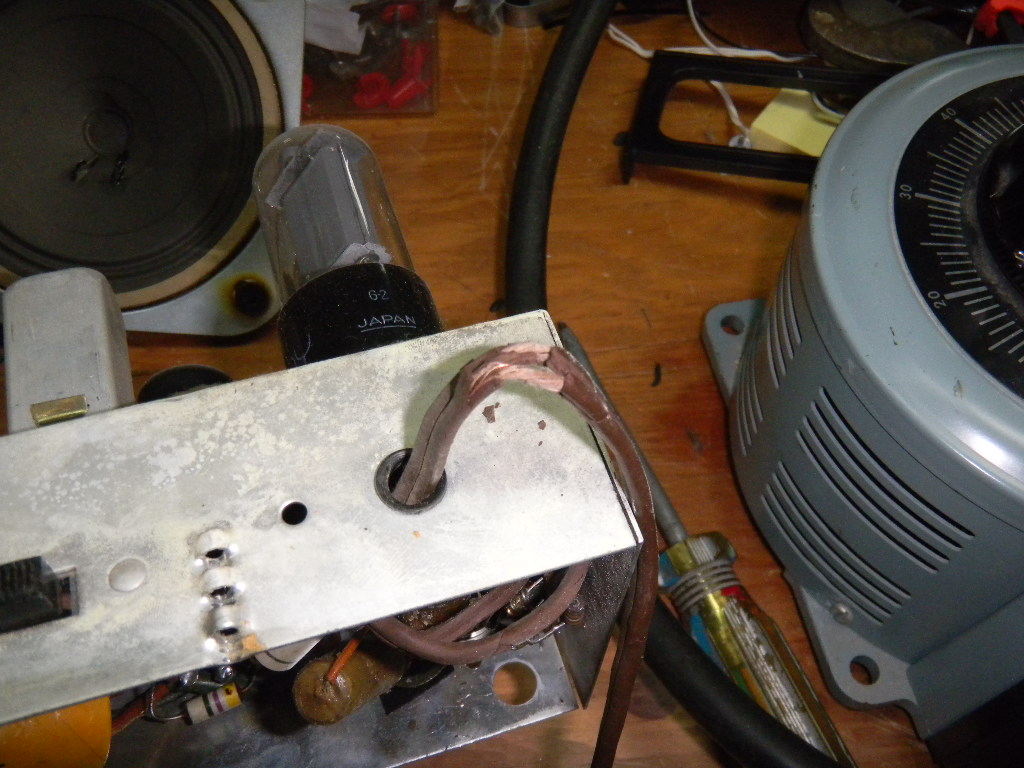
The power cord crumbles a bit more every time I touch it. Gotta change it out right away.
Image

I made a small video clip demonstrating the issue. You can sorta make out CHQT 880 in the receive audio.
http://sandbox.ahtr.net/DSCN0916.AVI
TRENT310
Advanced Member
 
Posts: 235
Joined: Tue Aug 07, 2007 11:40 pm
Location: Whitecourt/Edmonton, Alberta, Canada

Re: Tube radio repair

Postby jon » Sun Mar 13, 2011 9:27 pm

In high school, we each had to bring a tube radio to work on in Electricity and Electronics. Not one of them had a schematic in the case. Our first project was to draw one ourselves, from the actual radio.

While faulty capacitors, loose wires or a bad tube are the mostly likely cause of the hum, a quick fix may also work: ground the chassis. Because, one way or the other, you have almost certainly got a grounding problem.

But, don't take my word for it; it was just too long ago.

Doing a little looking, on a hunch, as I write this, it looks like this might be the standard 5 tube table radio chassis of the era:
http://en.wikipedia.org/wiki/All_American_Five

The shock hazard warning in that article reminded me of another quick fix for hum that often worked: reverse the power plug in the wall socket.
User avatar
jon
Advanced Member
 
Posts: 9262
Joined: Mon May 08, 2006 10:15 am
Location: Edmonton

Re: Tube radio repair

Postby TRENT310 » Sun Mar 13, 2011 11:04 pm

I suppose I could take the time and make a schematic diagram, so I can put it back together if I screw up. Several challenges though... I would need to know the pinout of the tubes, and how do you read those 6-dot components? Hopefully resistor colour code hasn't changed at least. Some capacitors are also hard to read because they're all waxed over.

1. I wish they still offered electronics courses at a high school level.
2. In my current telecommunications course, the principles and operation of vacuum tubes isn't actually part of the curriculum. Used to be.

So the audio power amplification stage is just single ended and not push-pull then?

The tube layout diagram specifies a 35L6GT, 35Z5GT, 12SQ7, two 12SK7s, and a 12BE6. I wonder if I can look up datasheets on these. I'm kinda familiar with transistor part numbers, but these tube part numbers don't really mean anything to me yet. Some of these models are mentioned in that Wikipedia article, and the specs match the Canadian edition notes. The article also says having two 12SK7s as IF would make it a 'AA6' variant. The generic schematic mentioned in that article might be a good starting point for me.

I thought about the grounding problem, but then I thought again and this radio must have been before the days of grounded electrical systems, or even polarized outlets... how could you determine which wire was neutral in order to tie to the chassis? A neutral-hot reversal would mean the chassis is also electrically live...
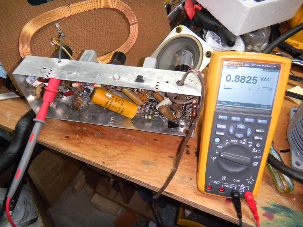
I grounded the chassis to the electrical system ground, and didn't help the case... and there is a voltage difference between the chassis and the electrical system ground. Then I flipped the plug around and that wasn't happening anymore. This cord set really needs to go.

Uh, yeah, line voltage (limited in this test by the variac but it was equal to line voltage going into the radio set). No wonder sparks were flying when I moved the ground clip. But it's not directly tied to the chassis because then that would have been a dead short, so at least it was current limited. Apparently this was a design feature? This is between B- and the metal case? What does the 'B' stand for? It's rectified power right?
Image

Flipped it around and no more voltage on the chassis. By the way, the buzz is still there when I push the switch towards the RCA connector, switches between radio and aux input.
Image
TRENT310
Advanced Member
 
Posts: 235
Joined: Tue Aug 07, 2007 11:40 pm
Location: Whitecourt/Edmonton, Alberta, Canada

Re: Tube radio repair

Postby TRENT310 » Sun Mar 13, 2011 11:19 pm

Actually, since you told me the name of this design, I've been able to find more information about it on the internet, very good explanations of what each component does.
So the big 50MFD cap in the middle is used to filter the 'B' voltage. I suspect that's something that needs to be changed.
TRENT310
Advanced Member
 
Posts: 235
Joined: Tue Aug 07, 2007 11:40 pm
Location: Whitecourt/Edmonton, Alberta, Canada

Re: Tube radio repair

Postby Mike Cleaver » Mon Mar 14, 2011 12:02 am

It's most likely the filter capacitor, the big yellow guy there with the three wires coming from it.
That means it's actually two capacitors inside one case.
The other, smaller ones are likely ok.
They don't make multisection caps any more (except for the metal ones that sit on top of the chassis, made as replacements for the ancient ones.)
You'll need to replace each section with a single electrolytic capacitor, being careful not to reverse the polarities.
The neg wire goes to ground, usually.
What you need are ones of the same capacitance as indicated on the old one at the same or a higher voltage rating.
It appears to be two sections at 50 volts but I can't see the capacitance of each section.
That's where I'd start.
You don't have a "hot chassis" model where one side of the line cord actually went to the metal box (Yikes!)
So you can put a three prong plug cord on the radio, with the green wire going to the chassis.
And be careful in there.
There are voltages around the rectifier tube that can kill.
Start with the new line cord (boy, that one is scary) and the filter cap replacement.
And the resistor colour code still is the same, after all these years.
Mike Cleaver Broadcast Services
Engineering, News, Voice work and Consulting
Vancouver, BC, Canada

54 years experience at some of Canada's Premier Broadcasting Stations
User avatar
Mike Cleaver
Advanced Member
 
Posts: 2085
Joined: Sat Apr 29, 2006 6:56 pm
Location: Vancouver

Re: Tube radio repair

Postby Neumann Sennheiser » Mon Mar 14, 2011 6:15 am

I expect a majority of the usual suspects here have a few old radios and other vintage players around the house. I have at least a half-dozen ranging from art deco bakelite countertops to a 1920's crank operated Edison disc player (the post- cylinder version that plays big chunky 1/4 inch thick discs) that still looks and works beautifully and, of course, the ubiquitous gigantic, ornate wood floor model with original call-letter labels on the pre-sets.
Some work better than others.
A separate thread with pictures from all of us might be a great idea.
"You don't know man! I was in radio man! I've seen things you wouldn't believe!"
User avatar
Neumann Sennheiser
Advanced Member
 
Posts: 1129
Joined: Sat Jun 24, 2006 10:43 pm
Location: Port Ludlow, Washington, USA

Re: Tube radio repair

Postby jon » Mon Mar 14, 2011 8:49 am

If you get desperate, there is a fellow in Edmonton who is an expert on antique radios:
http://www.edmontonjournal.com/days+bef ... story.html
User avatar
jon
Advanced Member
 
Posts: 9262
Joined: Mon May 08, 2006 10:15 am
Location: Edmonton

Re: Tube radio repair

Postby TRENT310 » Mon Mar 14, 2011 10:03 am

I was just looking around my collection of capacitors and all of my 50uF caps that are rated for >150V working voltage (so line voltage) are ones used to start induction motors, apart from the physical size issue of having 2 separate ones in there, would that be acceptable as a replacement?


This was probably a cost cutting design for that era but compared to today's cost cutting designs it makes this look like a solidly built piece of equipment...
TRENT310
Advanced Member
 
Posts: 235
Joined: Tue Aug 07, 2007 11:40 pm
Location: Whitecourt/Edmonton, Alberta, Canada

Re: Tube radio repair

Postby Mike Cleaver » Mon Mar 14, 2011 10:23 am

Yes, you can use those if you can fit them in physically.
As long as the capacitance is the same and the voltage is the same or higher, you're good to go.
OBSERVE the polarity though.
Nothing's worse than an exploding cap.
It was a space saving measure as you've guessed.
There were (and still are recreations) of two, three and even four section can capacitors, specifically made for resuscitating old equipment.
A modern electolytic cap won't cost you much if you want to use something smaller.
This likely will clear your hum problem but if it doesn't, come back and we'll see what else can be done.
Mike Cleaver Broadcast Services
Engineering, News, Voice work and Consulting
Vancouver, BC, Canada

54 years experience at some of Canada's Premier Broadcasting Stations
User avatar
Mike Cleaver
Advanced Member
 
Posts: 2085
Joined: Sat Apr 29, 2006 6:56 pm
Location: Vancouver

Re: Tube radio repair

Postby skyvalleyradio » Mon Mar 14, 2011 10:43 am

ditto what Mike sez: In my 2 working Hallicrafters S20-R HF receivers, I replaced all the old caps with electrolytics of the same values and this solves any hum issues. Ensuring that all tube sockets etc are getting good solid grounding where applicable also helps. Good luck with this project Neumann!!
User avatar
skyvalleyradio
Advanced Member
 
Posts: 1109
Joined: Fri Jul 14, 2006 1:16 pm
Location: The Goofy Islands

Re: Tube radio repair

Postby Anotherwpgguy » Mon Mar 14, 2011 12:11 pm

Super pressed for time or I'd add a few tips on the rstoration project. Hard to go wrong on that though. Component value tolerances were very wide.

Here is a great place for restoration materials everything from the power coming in through replacement line cords, through the whole system, and out the replacement speaker grill cloth .... http://www.tubesandmore.com/

I have lots of pictures I could add from my colection of goodies ... and the sad part is that I need to make room and will be getting rid of a lot of my antique radios .... BCB and ham equipment ... to make room for my model railway that I'll be building in the basement and trimming the radio collection to only the most unusual plus the high performance state of the art stuff like my Icoms.

Enjoy the Antique Radio Supply site.

Anotherwpgguy
User avatar
Anotherwpgguy
Advanced Member
 
Posts: 460
Joined: Sun May 24, 2009 8:46 pm
Location: West of Winnipeg

Re: Tube radio repair

Postby Mike Cleaver » Mon Mar 14, 2011 4:50 pm

Tubes and More is an awesome source.
I've used them for years for "hard to get" parts.
They also have a fairly large collection of schematics.
They have the multisection can capacitors I mentioned above.
I bought four for my RCA console several years ago.
They're also a great supplier for people who "DIY" their own tube gear.
Mike Cleaver Broadcast Services
Engineering, News, Voice work and Consulting
Vancouver, BC, Canada

54 years experience at some of Canada's Premier Broadcasting Stations
User avatar
Mike Cleaver
Advanced Member
 
Posts: 2085
Joined: Sat Apr 29, 2006 6:56 pm
Location: Vancouver

Re: Tube radio repair

Postby TRENT310 » Mon Mar 14, 2011 5:03 pm

I got a higher value cap, both higher capacitance and higher voltage rating. I'll put that in tonight and see if it works.

I'll bring it to electronics lab class tomorrow so I have access to more test equipment.
TRENT310
Advanced Member
 
Posts: 235
Joined: Tue Aug 07, 2007 11:40 pm
Location: Whitecourt/Edmonton, Alberta, Canada

Re: Tube radio repair

Postby TRENT310 » Mon Mar 14, 2011 10:10 pm

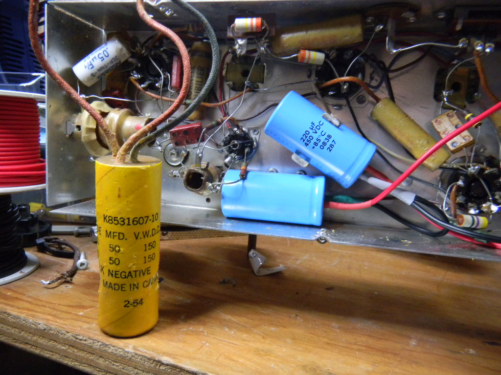
Cap swap worked out nicely. No hum at all when the volume is turned down (unlike the full amplitude buzz previously, no matter the volume control position), and some very slight background hum with audio, but that's fine, it could be anything, picking up electrical noise or whatever. (It's kinda like listening to CFRN 1260, which seems to always have 60Hz in the background all the time.)

Apparently the 50uF capacitor spec was already larger than average for this radio design, for 25Hz AC line operation. Well now it's got 220uF...

Image
The power cord was also swapped out. The old one kept crumbling when I was trying to remove it so I just cut it and desoldered the remaining bits. I note that it's a switched neutral design, with the hot going directly to the rectifier which is fine I guess, I will unplug it before messing with any of that. There's a high resistance between the chassis and any one of the AC lines, somewhere like 430k ohms. So there's probably going to be a very slight ground current. Like 270 microamps, and GFCI outlets probably won't like it, but so what.

How hot are the tubes supposed to run? The 35V voltage drop ones, 35Z5GT rectifier sure runs hot when at full line voltage as well as the 35L6GT AF final. That's normal though, right?

What's the IF alignment procedure for these?
TRENT310
Advanced Member
 
Posts: 235
Joined: Tue Aug 07, 2007 11:40 pm
Location: Whitecourt/Edmonton, Alberta, Canada

Re: Tube radio repair

Postby TRENT310 » Mon Mar 14, 2011 10:50 pm

I guess it needs heat to emit electrons, so that's a feature.

The radio has good low signal sensitivity, and it doesn't generate much internal noise. Audio is actually cleaner with weak signals than with local stations.
TRENT310
Advanced Member
 
Posts: 235
Joined: Tue Aug 07, 2007 11:40 pm
Location: Whitecourt/Edmonton, Alberta, Canada

Next

Return to Computer & Technology News

Who is online

Users browsing this forum: No registered users and 140 guests